Human laziness is momentum of progress.
I am too lazy change often antenna cables, seek their ends in mess on my table and toggle all the weird manual antenna switches again and again. One solution for cleaning my hamshack table and obtain as goal possible remotely operated hamshack is an automatic antenna switch.
Commercialy available things are even far of my budget or not fulfill my expectation about their functionality. So one nice evening I was start my own homebrew project.
Switch is intended for use with ICOM CI-V protocol. When is used alone with transceiver without PC control (CAT software, any logging software with CAT functionality), the “CI-V transceive” option in TRX setup shall be set to “ON”.
Control unit
Core of control unit is cheap and simple Arduino Nano board (available as cheap chinese clones on ebay or not so expensive originals in local shops). I was diving into my garbage bin, table drawers and waste under table in my workshop and collect some usefull things – several relays, 16×2 LCD panel, rotary encoder and nice new anodized aluminium box which is big enough for all this garbage. I was deciding not to made the PCB due to simplicity. The relay box do not need PCB too.
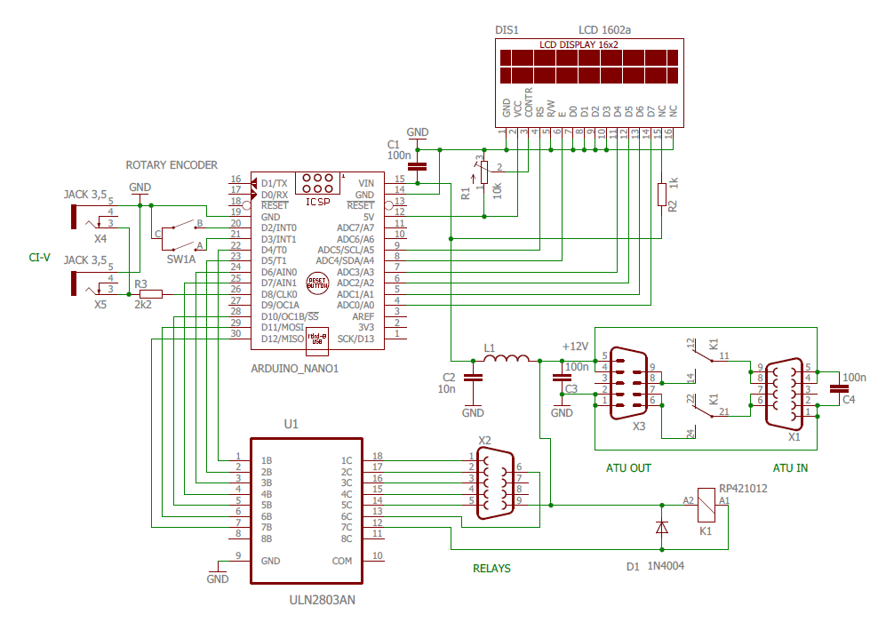
All capacitors are ceramic blocking, inductor L1 is an ferrite choke SMD inductor found in my drawer. Arduino is very sensitive to RFI induced in cables without filtering of power supply.
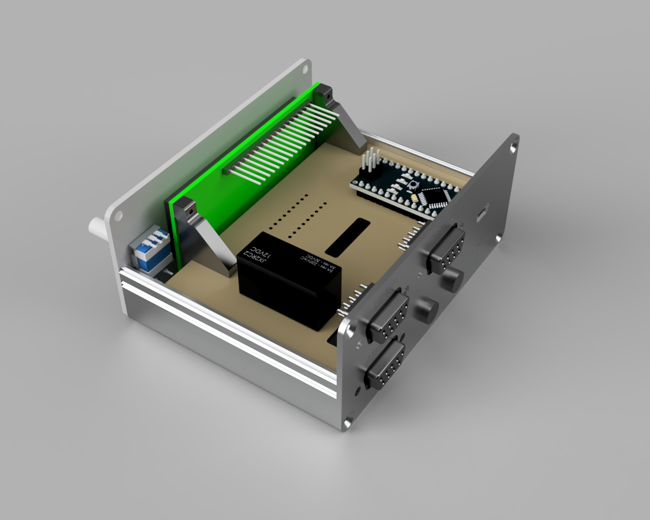
Control unit was realized as rats nest on table, code was writen and tested and I was start playing with mechanical construction. This task helps me solved an excellent Autodesk Fusion360 3D CAD. For hobby use it is free, just anual registration is needed. Of course, some time I was spent by learning to use it. I am often using it for construction of 3D things printable on 3D printer (of course, homemade 😉 ). 3D model of my aluminium box I have found on manufacturer’s website, some other components like Arduino Nano, LCD panel, encoder, connectors and relay I have found on Grabcad website and simple ones I construct myself directly in Fusion360. Then, I got 3D model of entire box assembly, what allowes me to make front and rear panel with holes and engraved texts and base plate from 1,5 mm thick GFK board on my CNC router (of course homemade too 😉 ).
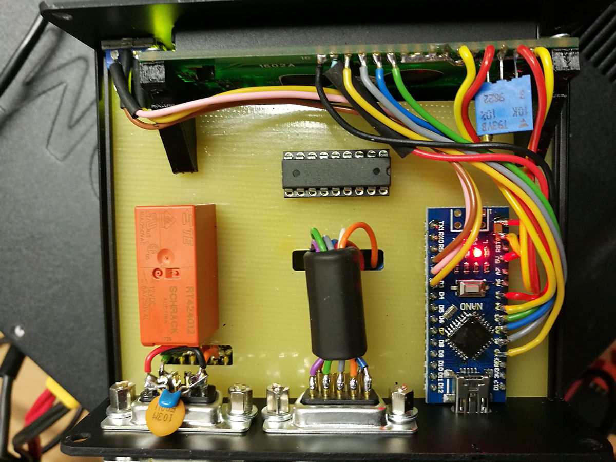
Components are allocated on GFK board and directly wired, nothing special. Holders for LCD panels are printed on 3D printer from plastic, screwed to board and display by screws (standard metric M2, M3, thread is cuted directly in plastic, or self tapped small screws can be used). Wires to relay box connector goes through EMI ferrite choke to prevent RFI comming through cable inside box.
Pictures of real construction:
 |
 |
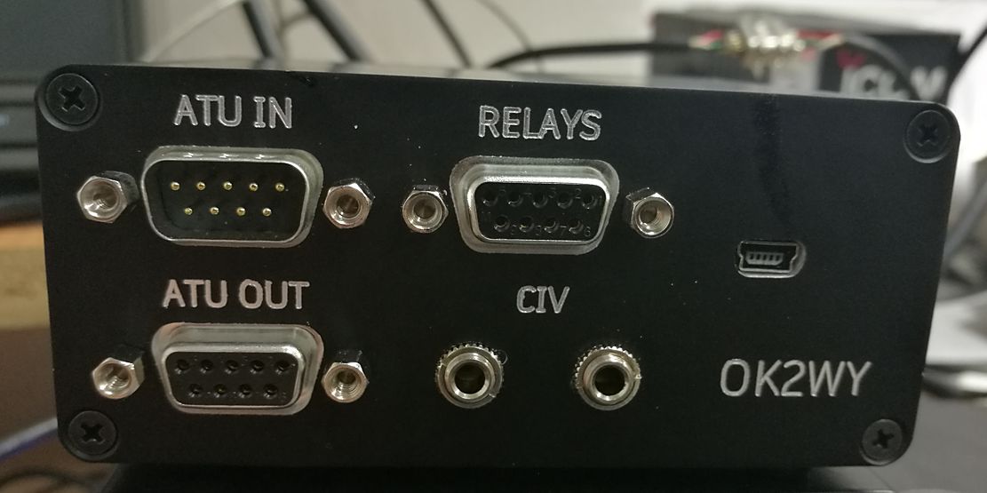 |
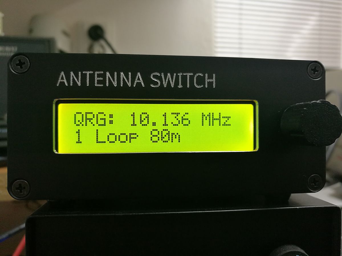
| inside look | Front panel | Rear panel |
Relay box
Relay box is simplest possible part of antenna switch. I have used an aluminium die-cast box with appropriate dimensions. It can be rain water resistant if it will be located connectors side down and appropriately shielded, because UHF connectors are not watertight. If you want to use it outside directly exposed by rain, choose sealed N-type connectors instead and do not forget drill small hole at lowest side of box, which allows condensed water from air humidity inside box drain out. I have used GFK board again, relays are glued by drop of cyanoacrylate glue to this board and wired directly in air. Cable to control box should be shielded type, shielding connected on both side to conductive boxes (conector body).
Pictures of real construction:
plastic parts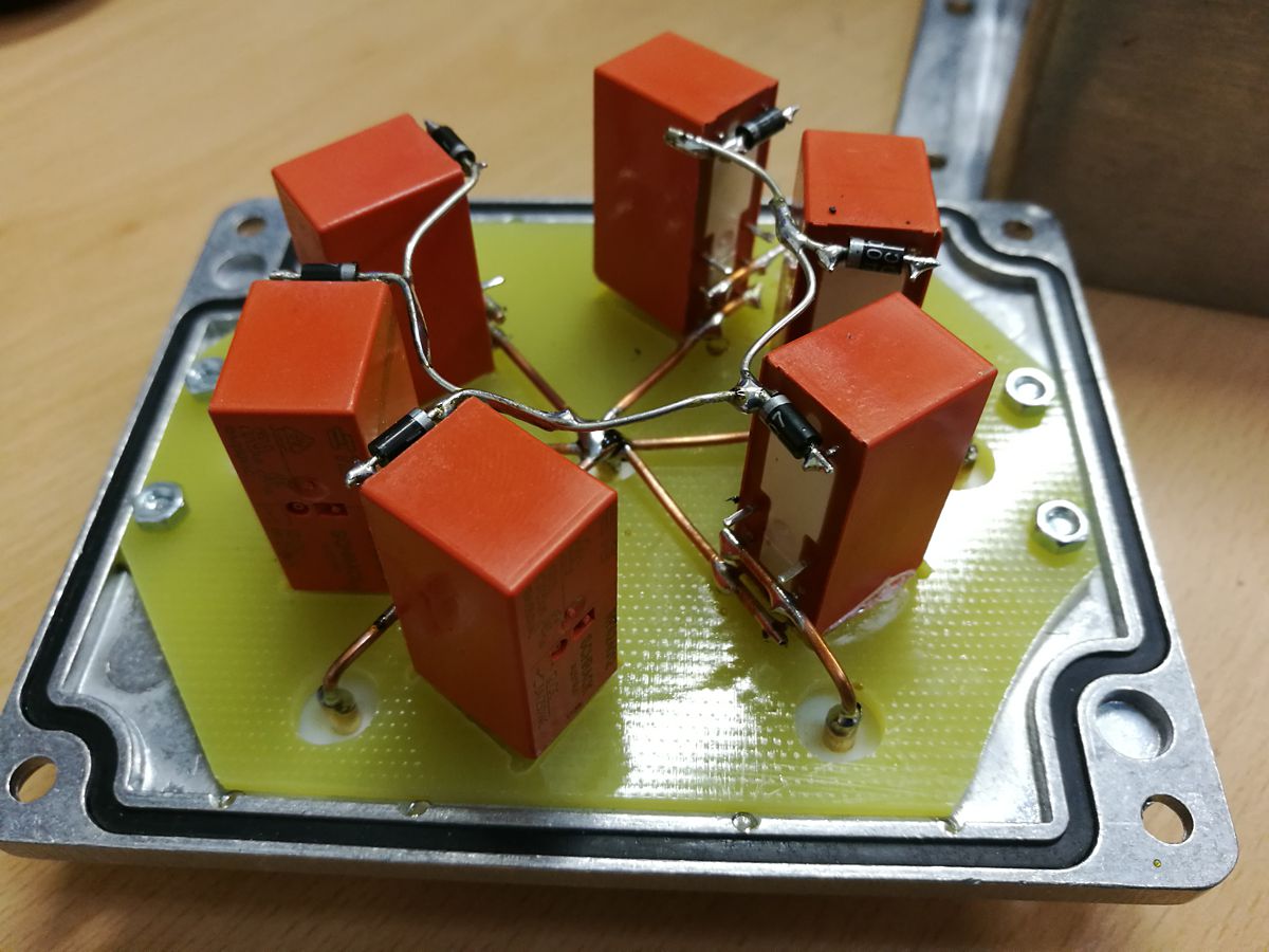 |
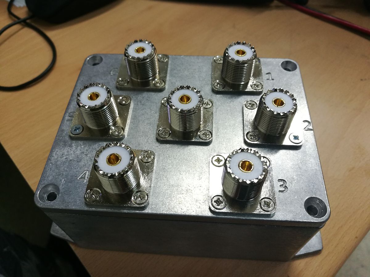 |
| inside look | connectors |
What else?
Following you find STL files of plastic parts for printing on 3D printer – display holder (2 pcs. needed) and knob for rotary encoder with D-shape shaft 6 mm in diameter. Recommended filament is ABS or PETG:
And last but not least, arduino code. Please read comments, you should understand how setup through serial terminal works. If not, download any serial terminal (for example PUTTY), set COM port where you have connected Arduino, set speed 38400 Baud, pres ENTER key and read instructions on your screen 😉 .
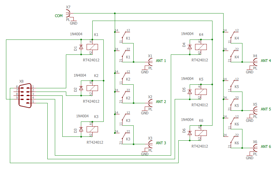
Schematics in PDF:
control box and relay box
Feel free to use this article yourself, but please do not use it for commercial purposes. I will not take any responsibility for injuries, natural disasters, divorces, damaged equipments, car accidents, lost kittens and missed DX QSOs happened due to usage of my construction 😉
Have fun with HAMradio!
73! de Jiri OK2WY (twisted_sour_fish) ok2wy.com